
La carrozzeria di una cabina, allo stato grezzo, è la struttura metallica non rifinita che precede la verniciatura, la vetratura, l'installazione degli interni e l'assemblaggio finale. La sua qualità dipende da molto più che dalla sola precisione dello stampaggio. I pannelli devono essere posizionati rispetto a un sistema di riferimento stabile, uniti con un apporto termico controllato e misurati prima che i processi successivi mascherino eventuali errori dimensionali. Un processo produttivo affidabile, pertanto, combina la precisione dello stampaggio, la progettazione delle attrezzature, la sequenza di saldatura, il controllo dimensionale e la preparazione alla corrosione.
Per i costruttori di veicoli e gli acquirenti di componenti per la carrozzeria, la questione fondamentale non è semplicemente se una cabina appaia squadrata dopo la saldatura. Il problema più importante è se i punti di fissaggio, le aperture delle porte, il telaio del parabrezza, la linea del tetto e le interfacce con il telaio rimangano entro le tolleranze di disegno approvate dopo l'intero ciclo di giunzione.
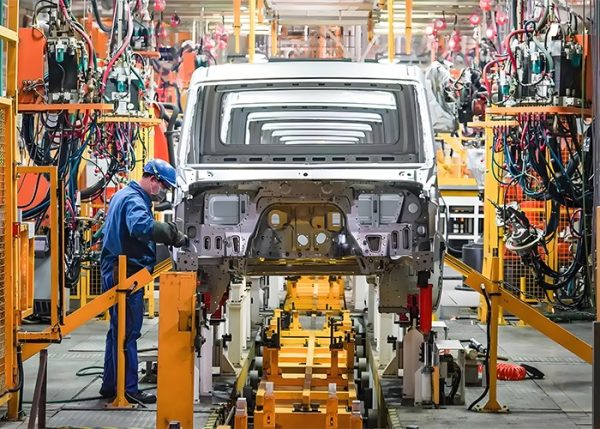
Quali sono le caratteristiche di una cabina di qualità con carrozzeria bianca?
Una cabina di qualità, di colore bianco, è una struttura metallica dimensionalmente stabile che può accogliere componenti successivi senza eccessive modifiche. Normalmente comprende la struttura del pianale, i pannelli laterali, il tetto, la parete anteriore, la parete posteriore, le aperture delle porte, l'apertura del parabrezza e i rinforzi strutturali.
Il termine "bianco" si riferisce alla carrozzeria assemblata e grezza prima della verniciatura. Non descrive il colore del metallo. In questa fase, gli ingegneri devono verificare diverse condizioni:
- I punti di fissaggio corrispondono al sistema di coordinate approvato.
- Le aperture per porte, parabrezza e servizi rimangono entro i limiti di progettazione.
- Le giunzioni saldate garantiscono una resistenza strutturale costante.
- Gli spazi tra i pannelli e le transizioni tra le superfici facilitano il successivo montaggio e la verniciatura.
- I rinforzi non creano distorsioni o interferenze locali.
- Le superfici sono idonee per operazioni di sigillatura e protezione dalla corrosione.
Un piccolo errore nella scocca grezza può trasformarsi in un problema più grave durante l'assemblaggio. Ad esempio, un rinforzo della cerniera posizionato in modo errato può causare l'abbassamento della portiera, mentre un telaio del parabrezza deformato può generare tensioni nel vetro o compromettere la tenuta.
Come il processo di produzione controlla la precisione
Il processo produttivo inizia con la formatura della lamiera e termina con la validazione dimensionale. Ogni fase influenza la successiva, pertanto la qualità non può essere ripristinata solo con l'ispezione finale.
La stampatura definisce la forma del pannello
La stampatura crea la geometria di base dei pannelli della cabina, comprese le flange, le nervature, le superfici di montaggio e le interfacce di rinforzo. Lo stampo deve controllare il flusso del materiale in modo che il pannello non presenti un eccessivo assottigliamento, increspatura o ritorno elastico.
Il ritorno elastico è una causa comune di variazione dimensionale. Dopo il rilascio della pressione di formatura, la lamiera tende a ritornare alla sua forma originale. L'effetto dipende dal tipo di materiale, dallo spessore, dalla geometria del pezzo, dalla profondità di imbutitura e dal design della flangia.
I controlli di timbratura più importanti includono:
- Posizione e diametro del foro
- Angolo della flangia
- Profilo del bordo
- Curvatura del pannello
- Torbidità locale
- Deformazione della superficie
- Ripetibilità tra lotti di produzione
Un pannello può apparire visivamente accettabile, ma risultare comunque difettoso una volta posizionato nel dispositivo di fissaggio. Per questo motivo, è fondamentale effettuare un controllo di compatibilità del dispositivo prima che un lotto consistente venga sottoposto a saldatura.
Gli elementi fissi creano la geometria di riferimento
I dispositivi di fissaggio definiscono la posizione relativa dei pannelli l'uno rispetto all'altro. Un sistema di posizionamento acustico solitamente suddivide le funzioni in tre aree:
- I punti di riferimento primari definiscono il piano principale.
- I localizzatori secondari controllano il movimento lungo un altro asse.
- I morsetti tengono fermi i pezzi senza forzarli in una posizione innaturale.
Un serraggio eccessivo può nascondere un problema di stampaggio. Quando i morsetti vengono rilasciati, il pannello potrebbe spostarsi indietro creando uno spazio vuoto o uno spostamento. Un serraggio insufficiente, invece, provoca movimenti durante la saldatura, alterando la geometria finale.
Il sistema di riferimento deve rimanere coerente dall'ispezione di marcatura al preassemblaggio e alla misurazione finale della carrozzeria. Se ogni stazione utilizza un punto di riferimento diverso, i risultati delle misurazioni potrebbero apparire accettabili localmente, mentre l'intera cabina accumula un errore.
Perché la sequenza di saldatura è importante per la qualità dell'assemblaggio della cabina
La saldatura unisce i pannelli stampati, ma il calore ne modifica anche la forma. Il metallo interessato si espande durante il riscaldamento e si contrae durante il raffreddamento. Se le saldature sono concentrate su un lato di un pannello sottile, la contrazione può spostare la struttura dalla sua posizione.
Ecco perché la qualità della saldatura dipende sia dall'integrità del giunto che dal controllo della distorsione.
L'apporto di calore deve corrispondere al giunto
Un calore eccessivo può causare bruciature, ammaccature, restringimenti localizzati e distorsioni visibili del pannello. Un calore insufficiente può provocare una fusione incompleta o giunzioni deboli. L'impostazione corretta dipende dal materiale, dallo spessore, dal tipo di giunzione, dalle condizioni dell'elettrodo, dalla velocità di saldatura e dal controllo dell'apparecchiatura.
Una linea di produzione stabile dovrebbe monitorare:
- Corrente e tensione di saldatura, ove applicabile.
- Tempo di saldatura
- Usura degli elettrodi
- Accesso e angolazione dell'arma
- Posizione della saldatura
- Livello di schizzi
- Aspetto congiunto
- Risultati delle prove distruttive o non distruttive secondo il piano di controllo approvato.
Una saldatura che supera un controllo visivo non è automaticamente strutturalmente affidabile. Le giunzioni critiche richiedono un metodo di ispezione e criteri di accettazione ben definiti.
La sequenza riduce la trazione strutturale
Una sequenza di saldatura bilanciata distribuisce il calore in modo uniforme sulla struttura. Saldature corte, lati alternati e saldature di posizionamento temporanee possono ridurre la concentrazione di stress termico. La sequenza esatta deve essere conforme al progetto della carrozzeria e alla documentazione di produzione approvata.
Di seguito viene presentato un utile confronto:
| Approccio di controllo | Vantaggio principale | Rischio principale | Uso appropriato |
| Saldatura continua in un'unica area | Adesione locale rapida | Maggiore accumulo di calore e deformazione | Profili spessi e stabili con validazione approvata |
| Sequenza di saldatura alternata | Migliore equilibrio termico | Requisiti di programmazione e ispezione più lunghi | Pannelli sottili e grandi strutture della cabina |
| prima saldatura a punti temporanea | Mantiene la geometria prima dell'unione finale | I chiodi deboli o posizionati male possono rimanere nascosti | Assemblaggi di carrozzeria multipannello |
| Forza di serraggio elevata | Riduce il movimento durante l'unione | Può mascherare il ritorno elastico e la distorsione di rilascio | Componenti stabili con forza di fissaggio verificata |
| Serraggio controllato con ispezione | Migliore separazione dei problemi relativi alle parti e ai dispositivi di fissaggio | Richiede ulteriori misurazioni | Avvio della produzione e assemblaggi sensibili alla qualità |
Controllo dimensionale prima dell'assemblaggio finale
L'ispezione dimensionale deve verificare le caratteristiche che influiscono su adattamento, funzionalità, sicurezza e processi successivi. Un piano di ispezione completo non prevede la misurazione di ogni superficie con la stessa priorità.
Le aree più sensibili di solito includono:
- Punti di fissaggio della cabina al telaio
- Rinforzi per cerniere e chiavistelli della porta
- Aperture del parabrezza e dei finestrini laterali
- Interfacce tetto e parete frontale
- Zone di montaggio del piantone dello sterzo e dei pedali
- Punti di fissaggio del sedile e del cruscotto
- Flange di tenuta
- Simmetria tra il lato sinistro e quello destro
Strumenti di misura a coordinate, dispositivi di controllo, misurazioni laser e calibri calibrati possono essere tutti utili. Il metodo deve essere adeguato ai requisiti di tolleranza e alla fase di produzione.
L'esito dell'ispezione dovrebbe distinguere tra:
- Un cambiamento di processo ripetibile
- Variazione casuale
- Un singolo componente danneggiato
- Usura degli impianti
- Disallineamento degli utensili
- Errore del sistema di misurazione
Questa distinzione è importante. Regolare un dispositivo per correggere un pannello danneggiato può creare un nuovo errore per ogni parte successiva.
Problemi comuni di qualità e le loro cause
Le aperture delle porte sono fuori posizione
Gli errori di apertura delle porte spesso derivano da un ritorno elastico, dall'usura dei componenti o da una sequenza di saldatura errata. Misurare solo il pannello esterno non è sufficiente. Le posizioni di cerniera, chiavistello, contropiastra e flangia di tenuta devono essere controllate insieme, poiché costituiscono un unico sistema funzionale.
Il montaggio del parabrezza non è uniforme
Un'apertura del parabrezza può cedere a causa di distorsioni degli angoli, variazioni dell'angolo della flangia o ritiro della saldatura. L'apertura deve essere controllata dopo che l'intera struttura circostante è stata saldata, non solo dopo la formazione dei singoli pannelli stampati.
Danni da schizzi di saldatura nelle aree di sigillatura
Gli schizzi su una flangia di tenuta possono impedire un contatto uniforme del sigillante. Possono anche creare un punto di accumulo che causa perdite localizzate dopo la verniciatura e l'assemblaggio. I requisiti di pulizia dovrebbero pertanto essere inclusi nel piano di qualità della saldatura, anziché essere lasciati agli operatori di assemblaggio finale.
La protezione dalla corrosione è disomogenea
I bordi in acciaio nudo, le cavità chiuse, le flange sovrapposte e le zone di saldatura richiedono particolare attenzione prima della verniciatura o del rivestimento. L'umidità intrappolata tra i pannelli sovrapposti può accelerare la corrosione se il drenaggio e la sigillatura non sono progettati correttamente.
Due verifiche pratiche prima di approvare un fornitore
Innanzitutto, richiedete un rapporto dimensionale redatto dopo l'intero ciclo di saldatura della scocca. Un rapporto basato sui singoli pannelli stampati non è sufficiente a dimostrare la stabilità della cabina assemblata.
In secondo luogo, confrontate i primi campioni con i pezzi prodotti dopo che la linea ha raggiunto la normale capacità produttiva. Il calore degli utensili, l'usura degli elettrodi, la temperatura del dispositivo di fissaggio e le regolazioni dell'operatore possono modificare i risultati dopo le prime unità.
È inoltre utile confermare:
- Stato di revisione dei disegni e delle norme di ispezione
- Lo stato di calibrazione delle apparecchiature di misura
- Piano di intervento per i componenti fuori tolleranza
- La tracciabilità delle saldature critiche
- Metodo di sigillatura e preparazione alla corrosione
- Il processo di approvazione per le modifiche a dispositivi o utensili
Capacità produttiva alla base di strutture di cabina uniformi
ShanDong TaiRui combina la produzione di componenti della carrozzeria con linee di stampaggio, linee di saldatura automatizzate, risorse per la lavorazione degli stampi e laboratori di collaudo. La sua capacità produttiva supporta la transizione dai pannelli formati alle strutture della carrozzeria assemblate, mentre la sua capacità di produzione automobilistica Fornire le basi produttive per lavori di giunzione e assemblaggio ripetibili.
Il controllo di qualità dovrebbe riguardare sia il processo che la struttura finita. sistema di garanzia della qualità automobilistica può collegare controlli dei materiali in entrata, ispezione in corso di processo, verifica della saldatura, misurazione dimensionale e rilascio finale. Per strutture di cabina personalizzate, capacità di ricerca e sviluppo nel settore automobilistico sono importanti anche perché le modifiche alla geometria del pannello, ai punti di fissaggio o alle attrezzature di produzione possono influenzare l'intero assemblaggio.
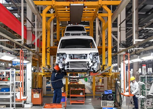
L'azienda è stata fondata nel 2003 e ha sviluppato competenze in diversi settori, tra cui componenti per carrozzeria, illuminazione automobilistica, veicoli speciali, stampaggio, saldatura, lavorazione di stampi e collaudo. Opera secondo un sistema di gestione della qualità IATF 16949 e fornisce supporto personalizzato per la pianificazione, lo sviluppo, la prototipazione e la produzione.
Domande frequenti
Qual è la differenza tra una carrozzeria per cabina (Cab Body in White) e un gruppo cabina (Cab Assembly)?
La carrozzeria di una cabina, allo stato grezzo, è la struttura metallica assemblata prima della verniciatura e dell'installazione degli interni. Un assemblaggio della cabina può includere componenti aggiuntivi come porte, vetri, finiture, cablaggi o altre parti montate, a seconda della definizione del progetto.
Quali sono i punti di ispezione più importanti in una cabina grezza?
I punti di fissaggio, le aperture delle portiere, le aperture del parabrezza, le flange di tenuta, le posizioni dei rinforzi e le interfacce del telaio meritano generalmente la priorità, poiché gli errori in queste aree influiscono sul successivo assemblaggio e sul funzionamento del veicolo.
Come si possono ridurre le distorsioni dovute alla saldatura nella struttura di una cabina?
Utilizzare un sistema di posizionamento stabile, controllare la forza di serraggio, bilanciare la sequenza di saldatura, monitorare l'apporto termico, ispezionare l'usura degli utensili di fissaggio e misurare il corpo completato dopo la saldatura. Anche la precisione della saldatura a punti è importante, poiché un posizionamento temporaneo errato può trasferire l'errore alla struttura finale.
Una cabina grezza dovrebbe essere approvata come un sistema dimensionale e di assemblaggio completo, non come un insieme di pannelli visivamente accettabili. Quando stampaggio, posizionamento, saldatura, preparazione per la sigillatura e ispezione vengono controllati simultaneamente, l'assemblaggio successivo si basa su fondamenta più solide e sono necessari meno interventi correttivi.